ddd-0.0 by Trenton Henry
This is basically the work in progress pre-release prototype. I am striving to get it up to the point of "useable".
Command summary
It's basically: ddd command args
ddd bfm2ddf - generates .ddf fonts in several sizes using json files from bitfontmaker2.com
srcpath -- the source .bfm font path containing the json exported from bitfontmaker2
dstpath -- the destination path of the generated dd font
To use this, you need to visit http://www.pentacom.jp/pentacom/bitfontmaker2/ and edit a font. When you export the data as jsob, save it into a .bfm file, then use it as the srcpath.
ddd mgk2ddf - generates some .ddf fonts in several sizes using imagemagick
srcpath -- the source ttf font path or imagemagick font name
dstpath -- the destination path of the generated dd font
This is experimental, to see if I could use ImageMagick to render antialiased fonts for me. It does work, but they look terrible as fat bits. When used on not-fat-bit window they look tolerable. I used an earlier variation in the pel based sqrsperiment and peldraw apps.
ddd demo bfmfonts - demonstrates the fonts created by bfm2bmf
Shows the bfmfonts. Use arrow keys to move through them, cmd-q to exit.
ddd demo mgkfonts - demonstrates the fonts created by mgk2bmf
ptsz -- the point size to demo
Shows the mgkfonts. Use arrow keys to move through them, cmd-q to exit.
ddd view - view a .ddd file
<fname> -- the name of the ddd file to view
[-metal] -- view with metal (default is dddre on GLFW on OpenGL)
Experimental. Currently using it to debug my software renderer, dddre, which renders using ddpe.
ddd stencil - edit a .ddt (2D template) stencil file
<fname> -- the name of the ddd stencil file to view
Edit a stencil, where a stencil is a 2D shape used as a template for radial sweeps (lathes), linear sweeps (lofts), and hull sweeps (like ships, model plane fuselages, ...). Stencils can also be converted to gcode for use with a CNC milling machine, via the ddt2g command.
Editing a stencil takes place on a 2D grid. It is 10 inches by 10 inches, which is more than twide s big as the envelope of my milling machine. The cursor snals to the nearest inch, tenth inch, hundredth inch, or thousandths inch depending on how you set the 'resolution'.
Mouse controls:
+------+------+------+------+------+
| | shft | ctrl | optn | cmnd |
+------+------+------+------+------+
| lft | | | | | select - dn, drag, up
+------+------+------+------+------+
| rgt | | | | | plot - dn, drag, up
+------+------+------+------+------+
| mid | | | | |
+------+------+------+------+------+
| mid | | | | |
+------+------+------+------+------+
| mid | | | | |
+------+------+------+------+------+
| whl | | | | | vscroll
+------+------+------+------+------+
| whl | x | | | | hscroll
+------+------+------+------+------+
| whl | | | | x | zoom
+------+------+------+------+------+
Keyboard controls:
cmd-a select all
cmd-c copy
cmd-x cut
cmd-v paste
ctl-h dup mirror horiz
ctl-v dup mirror vert
ctl-d dup mirror diag
m move (treats m key like mouse button. hold and move mouse)
cmd-z undo
CMD-z redo
r lower resolution
R higher resolution
y set axes of symmetry
delete delete
Yes, I am aware that this is crude and somewhat difficult to use well. It is a work in progress. Basically I am getting it to the point of making a thing I want to make with my mill. And, along the way, I identify the most tedious aspect of getting from here to there. And the I go focus on that next. So a lot of the UI is admittedly simplistic, but it will get better over time.
Devlog
02/05/22
I decided that it probably makes more sense to combine cnc into ddd and just manage one tool for now. So I added:
ddd ddcad - edit a .ddc (2D cad) stencil file
<fname> -- the name of the ddcad stencil file to view
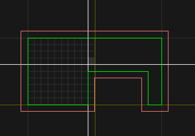
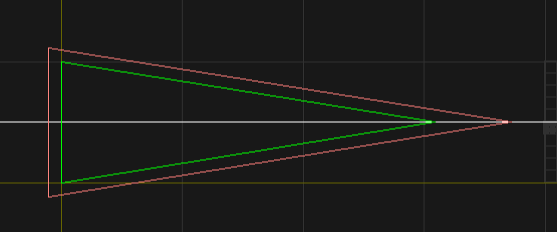
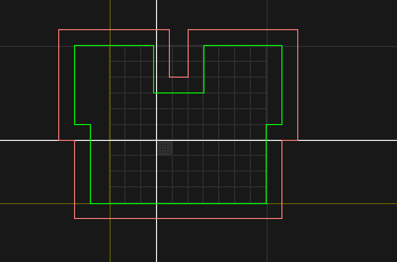
Now I have basic support for outlining polygons to create offset toolpaths. This allows me to position the cutting bit outside (or inside) of the shape perimeter one tool radius away so that the bit will cut around the part, not on the edge of the part, shich would make the resulting part too small.
Now ddcad will replace stencil. I wrots a quick hack to convert the existing .ddt files ito .ddc files because I was too lazy to redraw them.
In the images below the green line is the shape to be cut out, and the red line is the toolpath offset by the radius of the bit.


