Building Chaya's Robigotchi
by Trenton Henry
07/15/98
Copyright (C) 1998, Trenton Henry
Overview
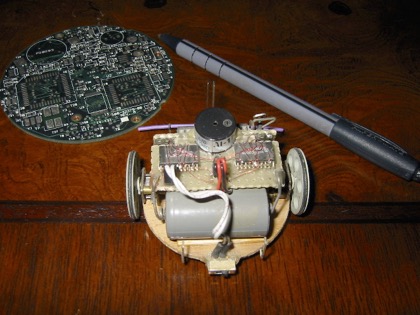
Robigotchi is a tiny robot built to my 10 year old daughter’s specifications. Chaya loves the Tamagotchi toys, and has been asking for a tiny "Robigotchi" for some time now. Her 10th birthday was a week away, so I decided to give it a try in the evenings after work. (My family was out of town during that time, and I was going to catch a plane and meet them, so I had to finish the project by the time I left for the airport.) Of course, I had no idea what a Robigotchi actually was supposed to be, but what the heck. She said "tiny" and "cute", and those became my design guidelines.
Clearly, since my time was very limited, I had to create something relatively simple. After dredging through my junk boxes and assessing my inventory, I settled on pretty much the simplest robot concept in the book; a round tail-dragger with two motors, two whiskers, two photocells, a beeper, and a small clear plastic dome. After an hour or so of digging around making the "Hmmmm" sound while I eyed sundry pieces of treasure/trash, I settled on a handful of parts. I just used a collection of stuff I had laying around. I didn’t have time to wait for stuff to come in the mail. I had no idea how long it would take to build this thing, and I really hoped to finish on time. So, I just used stuff that I had on hand.
At the time I began constructing the mechanical portions, I didn’t really have a good concept for the software. I continuously mulled ideas over in the back of my mind while I soldered a nd glued, trying to decide what a Robigotchi actually does. Of course, the software had to be very simple if there was any hope of finishing it on time. I wound up ditching several neural network "learning" algorithms and settling for a simple subsumption architecture implementing "collision evasion", "phototaxis", and "forward attraction" behaviors.
It took only an hour or so to write the code, which was very fortunate since when I went to test the Robigotchi I discovered that the whiskers didn't work reliably. I actually was building whiskers right up to the last minute; it took four or five tries to get it right! It turns out that the whiskers were the most technologically challenging aspect of the whole thing. Go figure:)
Anyhow, I managed to finish the Robigotchi with time to spare, and my daughter Chaya loved it. The rest of this article describes the whirlwind of construction and programming that resulted in Robigotchi.
[picture of daughter holding robot]
Mechanical
Motors
I chose a pair of 3v DC gear motors for their very small size, low RPM, and 45 ma no-load current rating. I wasn’t planning to carry any payload except a lithium camera battery, so I expected the motors to draw about this much current. I tested the motors by wiring them directly to a 3v lithium battery and measuring the current, which was around 40 ma. I decided I could live with that.
The gear motors I used were originally made by Canon, and sold as surplus through All Electronics for about $8 US. I only bought two, and when I later tried to order more they were gone. Sigh. There are available alternatives, though they are more expensive. Tiny micro-servos can be obtained for about $20 to $30 US, and can be hacked to spin continuously. Their motors run fine on 3v, but the electronics of most brands require 4.8v. Ripping out the electronics and using motor driver chips works well.
Maxon, MicroMo, Namiki, Portescap, and many other companies make tiny 3v gear motors. The only real drawback is the price. They can often be found in surplus catalogs for a reasonable price, but they are pretty expensive if you order them direct from the factory.
When I got back in town I discovered the Lego "Micro Motor". It is about the size of a 4 bump Lego cube. It draws 10 ma at 30 rpm with no load, and about 30 ma at about 20 rpm with a load. It runs on around 3v (though with little power or speed) up to 9v. My next project will use these little jewels, which only cost $11 US. Robigotchi could have made good use of them, but they weren't available at the time.
Chassis
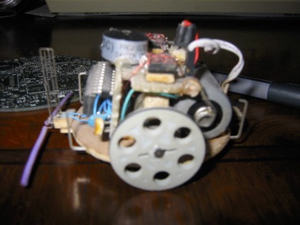
For the base, I used a circular wooden disk about 2 inches in diameter. (It was a little small for the plastic dome, but I solved that problem later.) A tiny drop of "super glue" held each motor in place quite nicely. With a little effort and a tiny bit more super glue I mounted a pair of wheels on the motor shafts. The wheels are the small Lego pulleys with six holes through them. I also installed a small o-ring on each pulley to act as tread. Rubber bands of the proper diameter would have worked just fine, but I didn't have any. At this point I had a dual motor robot base, but it was lacking a caster to support the tail end.
[top view of chassis showing motor placement]
There was no hope of finding a tiny caster wheel in my junk box. But, I remembered having seen other robots that used knobs or ping pong balls as casters. I wound up using a small wooden plug as the tail skid. The plug is the type that one finds covering the heads of screws on furniture. I had a box of them from a previous chair repair operation, but none were precisely the right thickness to make the robot balance with the base level. It took a little sanding to shorten one to the proper height, but it turned out just right. I used another drop of strategically placed super glue to mount the skid and then the base was ready for testing.
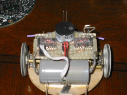
A 3v lithium camera battery is used to power the motors. I mounted it directly behind the motors, above the tail skid. At that point I used a couple of small clip leads to power up the motors and make sure that the chassis was operational. Everything seemed to be in order. The motors had no trouble carrying the weight of the battery, and the tail skid worked very well.
[side view of chassis showing wheels, tail skid, and battery]
Electronics
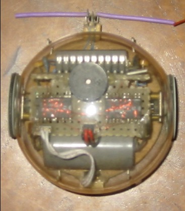
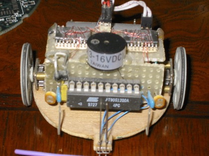
At this point I had a small mobile platform, but no control electronics. It took some thought to figure out how the circuit boards needed to be constructed and mounted to fit into the small space available. Eventually, I decided that the motor driver board should mount horizontally, parallel to the base, directly above the motors and the battery. The processor board mounts in the front of the robot, vertically. The two circuit boards are glued together along one edge, forming a sort of "L" shaped assembly that snuggles down over the motors. I did need to glue a couple of small balsa blocks on top of the motors to help support the circuit board assembly.
[photo or illustration of circuit boards]
Motor Drivers
The motor driver chips that I had available are the Harris HIP4020. These control one motor each, and have braking inputs, and outputs to indicate an over-current condition. I had no use for brakes on this robot, so I left the brake inputs unconnected. (I paid for this mistake later.) The over-current detection is set for 550 ma. Unfortunately, with a 40 ma motor, these are useless so I left them unconnected as well.
The biggest challenge involved the fact that the HIP4020 parts are surface mount packages. So, I glued small balsa shims under both chips, and then glued the shims to the circuit board. This effectively mounted the chips on the board with their pins raised up in the air where I could access them. (I considered simply flipping the chips on their backs and "dead-bugging" them, but I feared that I might make major wiring mistakes if I did so.)
I used a tool my father made for me a while back to wire up the motor control chips. This tool is a mechanical pencil with a spool mounted on the top. The spool is wrapped with teeny tiny wire, similar to motor winding wire. I think that it is called "Belden Wire". Anyhow, the free end of the wire feeds through the pencil body and out the tip. This allows very precise control over the wire, and facilitates the wiring operation.
[photo or illustration of useful tool]
Of course, it takes a very sharp, pointy soldering tip to avoid bridging between pins. It takes a little practice, and a lot of patience. I wrap the wire around the pin and then put a tiny drop of solder on the tip of the iron. The I heat the connection until the solder flows. The trick is to burn the coating off the tip of the wire to get a good solder joint. Since this is fairly tedious work, I make it a practice to ring out every connection with a meter as I go to make sure there are no cold solder joints. Once I had wired up the motor drivers, I used a pair of bent paper clips soldered onto the motor driver circuit board to reach down and contact the battery. At this point I was able to test out the wiring of the motor driver chips. Bizarre things were happening. The motors would run just fine, then suddenly stop, then run again. I checked all of the connections multiple times looking for the problem before it finally hit me; the braking inputs were left floating. The brakes were turning on and off. So, I hard-wired the brakes to ground and the problem went away. Details, details.
[extreme close up photo of motor drivers]
Processor
In keeping with the rest of the operation, when it came to the robot’s CPU, I used what I had. Fortunately, I have lots and lots of different processors in my junk box. But in this case I wanted to use a specific one, the Atmel AVR AT90S1200A. There are plenty of different varieties of this processor; I just happened to have this particular model on hand.
The AT90S1200A is a 20 pin processor with a RISC processor core, 32 registers, and 64 bytes of eerom. Its i/o pins can be configured as outputs, inputs with pull ups, or inputs without pull ups. It also has an analog comparator, two low power modes, and runs on 2.7 to 6v. It has internal reset circuitry, and a built in RC oscillator. The RC oscillator is not the most accurate thing around, but for my purposes it is perfect; especially since it saved having to put a ceramic resonator on the board. (I was running out of room).
Another very handy thing about the AVR is that it uses flash memory for program storage instead of ROM. That means that code can be programmed into the part immediately, without having to use an ultraviolet eprom eraser. Obviously, this is very important when time is critical and hard core debugging tools are unavailable. Using this processor enabled me to build a single chip (except for the motor drivers) robot controller; no power on reset circuit, no brown out detection, no ceramic resonator, and no voltage regulator. Since my goals included "small", this was just what the doctor ordered. (I even wound up with a little room to spare on the circuit board, so I added a small beeper.)
Atmel provides a free assembler, simulator, and debugger for the AVR family. These tools run under Windows 95, and are very professional. They have an evaluation board, with switches, LEDs, etc. for around $50 US. This board also doubles as a programmer for various flavors of the chip. There is tons of information available about these chips, the tools, and the programmer at www.atmel.com, so there is no point in describing it in detail here. If you are interested, look it up.
Sensors
Photocells
Robigotchi has two cadmium sulfide photo resistors mounted on the processor board as "eyes". Since the AT90S1200 does not have an analog to digital converter, I used a simple one-shot technique. A small capacitor is charged through the variable resistance. Timing how long it takes this capacitor to charge yields a rough estimate of the resistance of the photo resistor, which in turn gives an estimate of the brightness of the light falling on the detector. Electrical engineers may look at the schematic and realize that if the photo resistor has no resistance, then shorting the cap to begin the timing operations creates a dead short across the battery. Instead of adding a resistor in series to defend against this possibility, I simply made sure that the shorting operation happens for the minimum duration possible. I suppose that this could be considered bad form by many, but it works, and my daughter loves the robot, so I win regardless. Your mileage may vary.
Light sensors allow Robigotchi to perform behaviors with cool sounding names like "photo-taxis" (which just means "attraction to light"). They also help with navigation, since Robigotchi can use them to follow a shadow around the edge of an obstacle, sometimes avoiding a collision. However, when using just the eyes, with no other sensors, Robigotchi is something like a moth fluttering around a porch light; it keeps whack-smacking its head into things, never even realizing the damage. That’s why Robigotchi also has a pair of whiskers.
Whiskers
I am embarrassed to admit it, but the whiskers were actually the most frustrating, challenging, and interesting part of the entire project. Who would have thought that making a silly bumper on a tiny robot would be so difficult. (Of course, maybe its just me.) The plan was to make a pair of whiskers sticking out the front of the robot so it could detect obstacles and turn away from them. It seemed pretty simple to me, so I began rummaging through the treasure/trash collection making the "hmmm" noise again. I tried a number of switches, but they were all either too big, or too springy (the robot couldn't exert enough force to defeat the spring and close the switch).
So, I decided to bootleg an idea I had seen used on other robots; put a small metal spring around a metal stick, attached at one end with a small amount of insulation. This type of spring switch is fairly common, so I was sure that it was the proper solution. But, alas, the springs from ball point pens were too springy also. Robigotchi is too wimpy to consistently cause the spring to bend enough to contact the switch. I scoured the house for sacrificial toys and appliances that might contain "proper" springs, but there were none. I even tried making my own tiny springs out of winding wire, but I'll spare myself the embarrassment of relating how dismal a failure that turned out to be.
So, I harvested the little springs from a couple of dead 3.5" disks, attached long whisker-like wire extensions to one end, and soldered the other ends to a small circuit board. I arranged it so that the free springy ends passed between a set of metal posts; the other half of the switch. When something touched a whisker, the spring flexed and contacted a metal post, closing the circuit. This was a dramatic improvement over the previous attempts, but it still wasn't as good as I hoped and expected it would be. Robigotchi could still drive headlong into a wall and never know it. The springs were fairly strong, and they just didn't always work right. But, I was far enough along that it was time to write some code. So I tabled the whisker problem temporarily, and fired up my PC.
[illustration of several failed whisker attempts]
Software
I had no intentions of trying to advance the state of the art in robotic control algorithms (and indeed, I didn't:). Instead, my goal was to implement an approach that allowed Robigotchi to drive around in a shallow drawer (from an old desk) and avoid obstacles (building blocks). The first step was to write the start up code, and the parts that read the whisker inputs, read the photo resistor inputs, and control the motors. I think that the source code listing explains all of this fairly well, so I won't go into it here.
As for the "control" algorithm, the part that causes Robigotchi to "decide" what to do next, I chose a simple scheme based on the popular subsumption architecture pioneered Rodney Brooks. Boiled down to its bare essence, this scheme involves a set of programs that examine the sensor inputs, watch timers, etc., and decide whether or not they need to do something. Only one program gets to control the motors at a time, even if several programs are trying. Typically, the highest priority program gets to control the motors (and other "actuators"). When that program is through, a lower priority program takes control, etc.. The higher priority "behaviors" can "subsume" control from the lower priority behaviors. The book "Mobile Robots, Inspiration to Implementation" by Anita Flynn and Joseph Jones provides a far better discussion of subsumption than I could ever hope to. Go read it.
Robigotchi has three behaviors, or things it can do. The lowest priority behavior is just "drive forward". If nothing else is happening, Robigotchi drives forward. (While it could have sat motionless, contemplating the meaning of its existence, I thought that my daughter would appreciate a little more action.)
The second behavior is "turn towards the light". Much of the time the brightness of the light on either side of the robot is roughly equal, so Robigotchi thinks that he is facing the brightest light already. In this case the "drive forward" behavior is not subsumed by the "turn towards the light" behavior. But, when a shadow falls across one light sensor, or a bright light is turned on, the light sensors inform Robigotchi that he is not facing the light. When that happens, the "turn towards the light" behavior takes over and does its thing, even though the "drive forward" behavior is still trying to remain in control. The output from "drive forward" gets shunted.
The third, and highest priority behavior, is called "collision evasion". If the whiskers indicate a collision, "collision evasion" subsumes control and maneuvers the robot to escape from the obstacle. The actual evasion algorithm is fairly trivial. If the left whisker is bumped then turn right. If the right whisker is bumped then turn left. If both are bumped then back up. Surprisingly, this simple scheme works very well.
Once I got this all working, which didn't take very long since it is such as simple algorithm, I deployed Robigotchi for maneuvers on the proving ground. (Ok, I really stuck him into his drawer and flipped the power switch.)
Trial and Error
Something wasn't wired correctly. I became a little confused as to what the cause of the problem actually was, and mistakenly assumed that there was an inductive kick-back resetting the processor whenever the motors turned on. So, I abandoned the idea of powering everything off one battery and added a tiny 3v watch battery to power the processor. (When that didn't solve the problem a detailed wiring check uncovered the culprit.)
The bizarre (to me, anyhow) thing that resulted from this was that if the motor battery was switched into the circuit, but the processor battery was switched off, the robot still came to life and executed its program. The processor was powering up through the i/o pins. After a couple of phone calls I learned that this is pretty common with CMOS processors, and that I had not created a life form with a will of its own.
At this point, everything except the whiskers was operating correctly. Again I tried modifications to the springy things. Nothing seemed to work properly. Having pulled several large chunks of hair out, I gave up and tried to relax by strumming on a guitar. Nothing seemed to be going my way; the small string snapped with a "plinkity" sound. After spouting a few choice words that my mother hadn't taught me, a little light bulb went on over my head.
It turns out that guitar string makes an amazingly good whisker for a tiny robot. It took a couple of tries to bend up a pair of functional whiskers, but in the end I had a set of the best whiskers I had built yet. So I moved on to the finishing touches.
[illustration of the final version of whiskers]
Finishing Touches
Dome
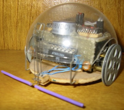
After spending the better part of a week on this project, I concluded that it needed a tiny plastic dome to protect the electronics, and to improve the cuteness effect specified in my daughter's design criteria. The problem was that the little dome I had (half of a clear "decorate it yourself" tree ornament) interfered with the wheels. So, it was necessary to sand "wheel wells" into the dome. This involved constructing a jig to guide the dome as I slid it back and forth along a dowel wrapped with sandpaper. It didn't turn out perfect, but it was pretty good for a first try.
[illustration of sanding jig]
Final Assembly
The last step was to mount the dome onto the chassis in such a manner that it could be easily removed. I wound up putting four tiny holes around the edges of the dome, and four strategically bent berg strip pins glued to the wooden base plate disk. Essentially, the bent pins are a little springy and can be manipulated so that they all poke through the holes in the dome. This holds it in place quite securely, with a little clearance above the wheels, and room for the whiskers and power switch. The dome can be easily removed for battery replacements, as well as periodic tinkering and improvements.
Conclusion
Building this robot wasn't quite like building a kit. However, it was a great deal of fun to whip up something from scratch using only materials already on hand. And, most importantly, Chaya loves it. I never found out just exactly what a "Robigotchi" is, but apparently I came close enough to the mark. Now, if I can just figure out how to build the robot mouse that my other kids want for Christmas...
Parts List
(2) 3v DC gear motor 45 ma no-load current, low rpm
(2) Harris HIP4020 For 3v DC motors, happened to have some
(2) CdS Photocell Had a bunch, chose the smallest ones
(2) 0.1uf cap For the photocell one-shot circuits
(1) 0.1uf cap Bypass cap for the processor
(1) SPST slide switch Tiniest power switch I could find in my box
(1) Sonic rated at 3-16v, built in oscillator
(1) 2" Clear plastic dome (happened to be exactly the right size)
(1) 3v Lithium camera battery (watch battery not necessary after all)
(1) Atmel AT90S1200a (Too many "good things" to list here; see text)
(1) Wooden "base plate" disc (actually an old wheel from a long dead robot)
(1) Wooden bump (one of the things that covers the heads of screws on furniture)
Misc As rqd. - wire wrap pins, paper clips, super glue, guitar string, balsa wood scraps, etc..
Source Code Listing
;;;;;;;;;;;;;;;;;;;;;;;;;;;;;;;;;;;;;;;;;;;;;;;;;;;;;;;;;;;
; Chaya's Teeny Tiny Birthday Robot
;;;;;;;;;;;;;;;;;;;;;;;;;;;;;;;;;;;;;;;;;;;;;;;;;;;;;;;;;;;
;
; 07/02/98 tbh initial version to verify hardware platform
; 07/03/98 tbh parameterized CDS read function
; modified for very simple subsumption
;
; this version uses a very simple sumpsumption architecture
; to control the robot. it has three 'canned' behaviors:
; collision evasion, phototaxis, and go forward; with
; respective priorities from highest to lowest. during
; each iteration the behaviors are invoked, in order of
; priority. if a behavior 'fires', it is manifested.
; there is no need to invoke the lower priority behaviors
; since they cannot fire. the behaviors are invoked until
; one fires. that is the one that is expressed. the
; priorities of the behaviors are implicit in the order
; that they are invoked. it is important to note that
; there is augmentation via a timer. however, the
; 'arbritrator', having a-priori knowledge of the
; priorities, also invokes the timing function. the
; 8 bit timer is used to time a nap; the processor uses
; sleep mode, and the timer interrupt awakens it.
; it might be better to try to implement the timers
; in the behaviors themselves, as it probably makes more
; sense. but, for now, this will have to do.
;
; pin out:
;
; 1 rst nc 20 vcc +3
; 2 pd0 dir0 19 pb7 nc
; 3 pd1 dir1 18 pb6 nc
; 4 xt2 nc 17 pb5 nc
; 5 xt1 nc 16 pb4 nc
; 6 pd2 (int0) nc 15 pb3 sw1
; 7 pd3 enb0 14 pb2 sw0
; 8 pd4 (t0) sonic 13 pb1 (ain1) cds1
; 9 pd5 enb1 12 pb0 (ain0) cds0
; 10 gnd gnd 11 pd6 nc
;
;;;;;;;;;;;;;;;;;;;;;;;;;;;;;;;;;;;;;;;;;;;;;;;;;;;;;;;;;;;
.include "1200def.inc"
.device AT90S1200
;;;;;;;;;;;;;;;;;;;;;;;;;;;;;;;;;;;;;;;;;;;;;;;;;;;;;;;;;;;
; can't use ldi on these registers
.DEF cds0 = r14
.DEF cds1 = r15
;;;;;;;;;;;;;;;;;;;;;;;;;;;;;;;;;;;;;;;;;;;;;;;;;;;;;;;;;;;
; can use ldi on these registers
.DEF tmp = r16
.DEF moto = r17
.DEF arg0 = r18
.DEF arg1 = r19
;;;;;;;;;;;;;;;;;;;;;;;;;;;;;;;;;;;;;;;;;;;;;;;;;;;;;;;;;;;
.MACRO FRWD:
ldi moto, 0xFE
.ENDMACRO
;;;;;;;;;;;;;;;;;;;;;;;;;;;;;;;;;;;;;;;;;;;;;;;;;;;;;;;;;;;
.MACRO BKWD:
ldi moto, 0xFD
.ENDMACRO
;;;;;;;;;;;;;;;;;;;;;;;;;;;;;;;;;;;;;;;;;;;;;;;;;;;;;;;;;;;
.MACRO LEFT:
ldi moto, 0xFF
.ENDMACRO
;;;;;;;;;;;;;;;;;;;;;;;;;;;;;;;;;;;;;;;;;;;;;;;;;;;;;;;;;;;
.MACRO RGHT:
ldi moto, 0xFC
.ENDMACRO
;;;;;;;;;;;;;;;;;;;;;;;;;;;;;;;;;;;;;;;;;;;;;;;;;;;;;;;;;;;
.MACRO BEEP:
ldi moto, 0xC7
.ENDMACRO
;;;;;;;;;;;;;;;;;;;;;;;;;;;;;;;;;;;;;;;;;;;;;;;;;;;;;;;;;;;
.MACRO STOP:
ldi moto, 0xD7
.ENDMACRO
;;;;;;;;;;;;;;;;;;;;;;;;;;;;;;;;;;;;;;;;;;;;;;;;;;;;;;;;;;;
RESET:
rjmp INIT
;;;;;;;;;;;;;;;;;;;;;;;;;;;;;;;;;;;;;;;;;;;;;;;;;;;;;;;;;;;
.ORG 0x02
TC0ISR:
; the timer isr is a do nothing - it just ends sleep mode
reti
;;;;;;;;;;;;;;;;;;;;;;;;;;;;;;;;;;;;;;;;;;;;;;;;;;;;;;;;;;;
INIT:
; initialize all of the port io, timers, irqs, etc.
; disable the comparator to save power - not using it
ldi tmp, 0x80
out ACSR, tmp
; port D is all outputs
ser tmp
out DDRD, tmp
; port B is all inputs
clr tmp
out DDRB, tmp
; use pullup on all but port pins B.0 and B.1
ldi tmp, 0xFC
out PORTB, tmp
; set the timer prescaler (pick whichever you like:)
; doesn't need to be done here. just load the
; desired prescaler into arg0 before calling NAP
;ldi tmp, 0x01 ; CK
;ldi tmp, 0x02 ; CK/8
;ldi tmp, 0x03 ; CK/64
;ldi tmp, 0x04 ; CK/256
;ldi tmp, 0x05 ; CK/1024
;out TCCR0, tmp
; enable timer interrupts
ldi tmp, 1<<TOV0
out TIMSK, tmp
; enable interrupts globally
sei
rjmp MAIN
;;;;;;;;;;;;;;;;;;;;;;;;;;;;;;;;;;;;;;;;;;;;;;;;;;;;;;;;;;;
NAP:
; pass in the prescaler as a parameter in arg0
out TCCR0, arg0
; clear the timer's up-counter
clr tmp
out TCNT0, tmp
; set the sleep enable bit
in tmp, MCUCR
sbr tmp, 1<<SE ; bit mask
out MCUCR, tmp
; oh mister sand man... sleep until timer irq
sleep
; return to sender, address hopefully known...
ret
;;;;;;;;;;;;;;;;;;;;;;;;;;;;;;;;;;;;;;;;;;;;;;;;;;;;;;;;;;;
; arg0 - (o) value is returned in this parameter.
; arg1 - (i) a bit mask containing a single set bit,
; corresponding to the io pin with the CdS. note that
; only bits 0 and 1 of port B are connected to CdS cells,
; so only use the values 0x01 or 0x02 for arg1.
;
; the CdS cells are read via one-shots. short the cap
; to ground, then time how long it takes for the cap
; to charge up through the CdS cell. clipped at 255.
;
CDS:
; make arg1-th bit an output
out DDRB, arg1
; drive arg1-th pin low to short the cap
in tmp, PORTB
com arg1 ; ones complement
and tmp, arg1 ; bit mask
out PORTB, tmp
com arg1 ; back to original
; make port B all inputs again
clr tmp
out DDRB, tmp
; use pullup on all but port pins B.0 and B.1
ldi tmp, 0xFC
out PORTB, tmp
; clear arg0
clr arg0
CDSWHILE:
; while (!cdspin && (cdsdelta < 255)) cdsdelta++
in tmp, PINB
and tmp, arg1 ; mask all but one bit
cpi tmp, 0x00 ; if its clear, keep counting
breq CDSINCR
ret ; arg1-th bit set - all done counting
CDSINCR:
inc arg0 ; still counting
ldi tmp, 0xFF
cpse tmp, arg0
rjmp CDSWHILE ; not maxed out yet
ret ; maxed out - clipped at 0xFF
;;;;;;;;;;;;;;;;;;;;;;;;;;;;;;;;;;;;;;;;;;;;;;;;;;;;;;;;;;;
; return carry clear if no output
; return carry set if output
;
EVADE:
; if both bumpers active then backup
; if left bumper active turn right
; if right bumper active turn left
in tmp, PINB
andi tmp, 0x0C
cpi tmp, 0x04
breq EVLT
cpi tmp, 0x08
breq EVRT
cpi tmp, 0x00
brne NADA
BKWD
sec ; set carry
ret ; with carry set
EVLT:
LEFT
sec ; set carry
ret ; with carry set
EVRT:
RGHT
sec ; set carry
ret ; with carry set
NADA:
clc ; clear carry
ret ; with carry clear
;;;;;;;;;;;;;;;;;;;;;;;;;;;;;;;;;;;;;;;;;;;;;;;;;;;;;;;;;;;
; return carry clear if no output
; return carry set if output
;
PHOTOTAXIS:
; read the left photocell
ldi arg1, 0x01
rcall CDS
mov cds0, arg0
; read the right photocell
ldi arg1, 0x02
rcall CDS
mov cds1, arg0
; decide which reads brighter
cp cds0, cds1
brsh RT ; cds0 < cds1
LT:
sub cds1, cds0
mov tmp, cds1
cpi tmp, 0x16 ; difference < epsilon?
brsh TLT ; no, turn left
clc ; clear carry
ret ; yes, no action
RT:
sub cds0, cds1 ; cds1 < cds0
mov tmp, cds0
cpi tmp, 0x16 ; difference < epsilon?
brsh TRT ; no, turn right
clc ; clear carry
ret ; yes, no action
TLT:
LEFT
sec ; set carry
ret ; with carry set
TRT:
RGHT
sec ; set carry
ret ; with carry set
;;;;;;;;;;;;;;;;;;;;;;;;;;;;;;;;;;;;;;;;;;;;;;;;;;;;;;;;;;;
; return carry clear if no output
; return carry set if output
;
WANDER:
; if timer0 count < 2 do nothing
; else go forward
in tmp, TCNT0
cpi tmp, 0x02
brlt WRET
FRWD
sec ; set carry
ret ; with carry set
WRET:
clc ; clear carry
ret ; with carry clear
;;;;;;;;;;;;;;;;;;;;;;;;;;;;;;;;;;;;;;;;;;;;;;;;;;;;;;;;;;;
MAIN:
BEEP
out PORTD, moto
ldi arg0, 0x04 ; CK/256
rcall NAP
STOP
out PORTD, moto
ldi arg0, 0x04 ; CK/256
rcall NAP
LOOP:
rcall EVADE
brcc DOPHOTO ; behavior didn't fire
ldi tmp, 0xC7 ; behavior did fire
out PORTD, tmp ;beep on bump
ldi arg0, 0x01 ; CK
rcall NAP
out PORTD, moto
ldi arg0, 0x05 ; CK/1024
rcall NAP ; snooze to extend turning duration
rjmp LOOP
DOPHOTO:
rcall PHOTOTAXIS
brcc DOWANDER ; behavior didn't fire
out PORTD, moto ; behavior did fire
rjmp LOOP
DOWANDER:
rcall WANDER
brcc LOOP ; behavior didn't fire
out PORTD, moto ; behavior did fire
rjmp LOOP
;;;;;;;;;;;;;;;;;;;;;;;;;;;;;;;;;;;;;;;;;;;;;;;;;;;;;;;;;;;
;eof
Additional Photos
Added 07/30/03 in response to several requests for more information.
